




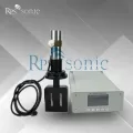

Ever tried to understand a 15kHz ultrasonic transducer and felt like it was actually *you* being vibrated at 15kHz? Wires, waves, and weird diagrams can turn a simple question into a full-blown lab headache.
Let’s fix that by breaking the 15kHz ultrasonic transducer working principle into clear, simple steps—how electrical energy turns into mechanical vibration and then sound—while following proven acoustic guidelines from standards like ISO 18431.
🔊 Basic structure of a 15kHz ultrasonic transducer and key components
A 15kHz ultrasonic transducer converts electrical power into strong mechanical vibration. Its structure keeps vibration stable, focused, and safe for long industrial cycles.
Most designs include a durable metal housing, piezoelectric ceramics, a pre‑stressed bolt, and a horn that transfers energy to the workpiece with minimal loss.
1. Front driver and horn
The front driver and horn focus vibration into the welding area. Their shape and length match 15kHz resonance for maximum transfer and low stress.
- Material: usually titanium or aluminum
- Function: amplify and direct vibration
- Design: tuned to half‑wavelength at 15kHz
2. Piezoelectric ceramic stack
The core of the 15kHz ultrasonic transducer is the piezo stack. It expands and contracts under alternating voltage and creates strong axial vibration.
- High electromechanical coupling
- Stable capacitance and low loss
- Precise thickness to meet 15kHz
3. Backing mass and prestress bolt
The backing mass and center bolt apply constant pressure to the ceramics. This keeps vibration linear and stops cracking during high‑power welding.
| Part | Main role |
|---|---|
| Backing mass | Balance vibration node, add stiffness |
| Prestress bolt | Clamp stack, prevent fatigue |
4. Electrical connectors and cooling path
Connectors deliver power from the generator and safely route it to the ceramics. Cooling paths remove heat for stable long‑term operation.
- Insulated terminals or flying leads
- Air or water cooling channels
- Sealing to block dust and oil
⚙️ Step‑by‑step conversion of electrical energy into high‑frequency mechanical vibrations
At 15kHz, the generator, transducer, and horn work together. They turn controlled electrical power into repeatable high‑amplitude motion for welding or cutting.
Understanding this chain helps engineers choose the right High Amplitude Dukane Ultrasonic Transducer Piezoelectric Converter and match it to the horn and fixture.
1. Signal generation and power drive
The ultrasonic generator creates a 15kHz sinusoidal signal and boosts it with a power amplifier. Output voltage and current follow the transducer impedance.
- Auto‑tracking keeps frequency near resonance
- Soft‑start reduces shock to ceramics
- Real‑time power monitoring improves safety
2. Electro‑mechanical conversion in ceramics
Alternating voltage causes the piezo stack to expand and shrink along its axis. This motion is small but very fast, exactly at 15kHz.
| Parameter | Typical value |
|---|---|
| Frequency | 15kHz |
| Strain | Micrometer level |
| Phase | Locked to drive signal |
3. Mechanical amplification in horn
The horn converts small ceramic motion into larger tip amplitude. It uses geometric gain while keeping stress inside safe material limits.
- Step, exponential, or catenoidal profiles
- Higher amplitude at smaller cross‑section
- Node placement near flange
4. Energy transfer to the workpiece
Vibration reaches the workpiece as pressure and friction. Local heat forms a melt layer and creates a strong welded joint without extra glue or screws.
- Force and amplitude must match material
- Cycle time is usually under seconds
- Consistent pressure improves bond quality
📡 Resonance, wavelength, and why 15kHz is used in industrial applications
At 15kHz, the transducer can deliver very high amplitude and force, ideal for thick plastic parts and some light metal welding tasks.
This frequency balances mechanical strength, tooling size, and acceptable airborne noise in many automotive and appliance applications.
1. Resonance and half‑wavelength design
The stack and horn length are usually one or multiple half wavelengths at 15kHz. This keeps stress low and amplitude high at the working face.
| Part | Approx. length rule |
|---|---|
| Transducer | λ/2 at 15kHz |
| Horn | λ/2 or 3λ/2 |
2. Wavelength in solids and vibration pattern
In metals, the 15kHz wavelength is several centimeters. Nodes and antinodes appear along the horn and guide where to place flanges and clamps.
- Nodes: minimal motion, good for mounting
- Antinodes: maximum motion, good for welding
3. Industrial reasons to choose 15kHz
Engineers choose 15kHz when they need strong penetration and large amplitude. It suits large parts better than higher‑frequency systems like 40kHz.
- Higher amplitude capability
- Better for thick or rigid plastics
- Common in automotive bumpers and dashboards
🧪 Factors affecting efficiency: material properties, impedance matching, and heat management
System efficiency depends on ceramic quality, metal selection, precise impedance matching, and how well you control heat under heavy duty cycles.
Engineers often compare 15kHz models with a High frequency ultrasonic transducer 40Khz piezo-electric converter to choose the best balance of power and resolution.
1. Material properties and mechanical losses
Ceramic and metal damping directly affect Q‑factor. Low internal loss keeps vibration strong and reduces the power needed for the same amplitude.
| Property | Impact |
|---|---|
| Density | Changes resonant length |
| Loss factor | Higher loss means more heat |
2. Electrical and acoustic impedance matching
Good matching means more input power becomes useful vibration. Mismatch shows up as reflected power, unstable amplitude, or excess heating.
- Generator tunes to transducer impedance
- Horn shape matches load stiffness
- Fixture must not clamp vibration nodes
3. Heat build‑up and cooling design
Heat reduces ceramic life and detunes resonance. Designers add cooling paths and choose materials that handle long, hot cycles safely.
- Use airflow around the stack
- Limit duty cycle at very high power
- Monitor temperature at the back mass
🛠️ Maintenance tips and why Powersonic 15kHz transducers provide stable performance
Stable 15kHz welding depends on good design and regular checks. Powersonic transducers focus on strong structure, accurate tuning, and safe heat control.
They also pair well with systems using a 40 Khz continuous work ultrasonic welding transducer for film sealing when plants need mixed‑frequency production lines.
1. Daily inspection and torque checks
Check the front face, horn, and cable every shift. Confirm bolt torque with a calibrated wrench to prevent loosening and micro‑gaps.
- Look for cracks or burn marks
- Clean surfaces with soft solvent
- Do not scratch the radiating face
2. Monitoring frequency drift and power trends
Watch the generator for rising power at the same amplitude or a shift in resonance. These signs can show wear, cracks, or loose joints.
| Symptom | Possible cause |
|---|---|
| Higher idle power | Contamination or detune |
| Frequent alarms | Crack, overload, or bad clamp |
3. Design strengths of Powersonic 15kHz units
Powersonic uses high‑grade ceramics, robust bolts, and well‑tuned metal stacks. This combination offers long life, repeatable amplitude, and low maintenance cost.
- Strict frequency tolerance control
- Good heat resistance at high duty
- Stable performance across wide loads
Conclusion
A 15kHz ultrasonic transducer turns controlled electrical energy into powerful vibration for welding, cutting, and forming. Its structure, materials, and tuning all shape performance.
By understanding resonance, impedance, and heat control, engineers can pick reliable 15kHz solutions, extend tool life, and keep weld quality stable in demanding production lines.
Frequently Asked Questions about 15Khz ultrasonic transducer
1. What is a 15kHz ultrasonic transducer used for?
A 15kHz ultrasonic transducer is mainly used for welding large or thick plastic parts, inserting metal pins, and some light metal or composite applications.
2. Why choose 15kHz instead of 20kHz or 40kHz?
15kHz offers higher amplitude and force, which helps when parts are big, rigid, or need deeper energy penetration than higher frequencies can provide.
3. How long can a 15kHz transducer run continuously?
Run time depends on power level, cooling, and design. With proper heat management and correct loading, quality units can support long production shifts.
4. How do I know if my transducer is failing?
Signs include cracks, unusual noise, hot spots, higher idle power, frequent generator alarms, or poor weld quality even with correct settings.
5. Can I use the same horn on different 15kHz transducers?
Only if the frequency, thread, and mechanical design match. Always check resonance and re‑tune the system after changing either horn or transducer.